Magnetic reed switches control the flow of electricity in a circuit without requiring an external power source. They are engineered to function through proximity to a magnetic field, so the actuator (the source of the magnetic energy) is simply a magnet paired with a sensor or a switch.
Typically, a reed switch consists of a pair of electrical contacts sited on a magnetic metal reed and enclosed in a protective glass casing. These flexible switches can open and close circuits using AC and DC voltage.
Magnetic reed switches are preferred in many industries because of their wide range of benefits. This article will discuss magnetic reed switches’ common applications and advantages.
Common Applications of Magnetic Reed Switch
Because it is versatile, a magnetic reed switch can be applied to various industries, from home appliances to automotive. Particularly, this magnetic switch can be found in the following battery-operated devices:
Laptops and Mobile Phones
Usually used in clamshell designs and cases, magnetic reed switches allow the screen to turn off when the lid is closed.
Tamper-Proofing Systems
Magnetic reed switches are ideal to use with security systems. They function as proximity sensors that trigger an alarm when the magnet moves away from the switch.
Automobile Doors
As long as a proximity sensor is present, magnetic reed switches can power car doors and the lights connected to refrigerator doors.
Auto Shut-Off Devices
Magnetic reed switches are installed in fluid level sensors and thermal cut-offs in dishwashers, washing machines, and showers.
Measuring Devices
Anemometers used to measure wind speed are operated with magnetic reed switches. They can also power speed sensor devices on bicycle wheels, car gears, and treadmills.
Safety Features in Devices
Magnetic reed switches are a safety feature in devices like food processors and power tools. They help prevent these devices from completely turning on when a lid, guard, or other component is not correctly placed.
Environments With Explosive Gases or Chemicals
Because magnetic reed switches are encased in protective glasses, any sparking from the switching action stays within the casing, preventing accidents in environments with explosive gasses and chemicals.
Benefits of Magnetic Reed Switch
A permanent magnet often powers a magnetic field in a reed switch. However, a current-carrying wire or coil may be used as an alternative. These switches are more cost-efficient than other electrics and consume less power, resulting in low mechanical wear and a longer operational lifespan.
Further, the switches don’t need to be physically accessed to control the electricity in the circuit, reducing the potential for electrical interference. Mechanical reed switches are also durable, reliable, compact, lightweight, and highly customizable in terms of precision and sensibility.
Finally, magnetic reed switches are sustainable and safe to use in hazardous environments because they are enclosed hermetically in glass cases. Hence, they are less vulnerable to corrosion.
Reliable Magnetic Reed Switches at Magnelink
For over 30 years, Magnelink has provided outstanding service and top-notch magnetic switches to clients from diverse industries! Our dedication and extensive experience allows us to supply dependable, innovative, and affordable products to our consumers, such as magnetic reed switches in a broad spectrum of housings:
MLA Housing
MLE Housing
MLF Housing
MLG Housing
MLH Housing
MLL Housing
MLM Housing
MLP Housing
MLQ Housing
MLT Housing
MLU Housing
At Magnelink, we value customer collaboration to deliver various requirements and needs. Contact us to partner with Magnelink! You may also call us at 800-638-0801.
MagneLink designs and manufactures magnetic switches for customers in a broad range of industries. We specialize
Click to Expand
in the development of custom-designed magnetic switches engineered to meet particular application requirements. Our extensive selection of switches includes high-performance magnetic limit switches in various designs and configurations.
What Is a Traditional Limit Switch?
A limit switch is an automatic sensor assembly that requires direct physical contact to detect the position of an object or material. It is commonly used to monitor the presence/absence, proximity, and/or movement of items or materials within a system. Based on what it detects, an actuator opens or closes the electrical contacts, which automatically stops or starts the flow of electricity to connected equipment. This capability makes limit switches ideal for use in applications where strict limits must be observed.
What Is a Non-Contact Magnetic Limit Switch?
Non-contact magnetic switches are similar to traditional limit switches, but with the added advantage of operating without requiring physical contact between the switch and actuator. This added feature makes a non-contact magnetic switch a better performer in harsh or dirty environments, as well as making it more difficult to override. A non-contact magnetic limit switch also has a longer lifespan thereby reducing potential down-time for equipment repair.
How Does a Limit Switch Work?
The original purpose of limit switches was to monitor the movement of objects or materials within a system and stop their progression at a pre-set limit without the need for direct human intervention. They perform this function by having an actuator that breaks an electrical connection when an object or material comes into contact with it. This stops the operation of the equipment and, consequently, the movement of the load.
In other applications, a limit switch may make an electrical connection when an object or material comes into contact with it. This activates a connected device or system, enabling it to perform the necessary function for the situation.
Components of a Limit Switch
A standard limit switch consists of an actuator with an operating head, switch body, and electrical terminals.
The operating head transmits the linear or rotary force from contact with the triggering object to the actuator.
The actuator opens or closes the switch in response to the application or removal of force.
The switch body contains the switch contact mechanism that opens or closes the connections between electrical terminals.
The electrical terminals connect the switch to the electrical circuit it is controlling.
Industrial applications often require highly durable and reliable switches that can withstand heavy use without compromising accuracy. Limit switches can be customized to meet the needs of particular equipment and operations. By adjusting the size, mounting, stroke rate, electrical rating, and operational force of the switch, you can ensure dependable, safe equipment operation even in harsh industrial conditions.
Types of Limit Switches
There are many types of limit switches, each of which offers unique characteristics that make it suitable for different uses and environments. They can be divided into four categories based on the operating head design and actuation method:
Non-contact magnetic limit switch: Non-contact magnetic limit switches are highly responsive switches that are controlled using a magnet actuator on a moving component of the equipment (i.e. door, gate, piston). The actuator triggers the switch when in close proximity to it. The switch can then electrically trigger alarms, shutoffs, etc. Non-contact magnetic limit switches offer a quick response time, making them an excellent choice for applications in door switches, elevators, light switches, lifts, conveyors, pressure switches, and temperature switches.
Whisker limit switch: Whisker limit switches have a long flexible spring arm (i.e., whisker) that bends when an actuating force is applied and springs back to its normal position when it is removed. They are often used in conveyor and assembly line applications, where they can monitor the flow and placement of materials and sound an alarm if items are out of place.
Roller limit switch: Roller limit switches use a roller on a stationary shaft to measure the flow of material or the number of items passing down a line or conveyor. They measure item quantity, volume, or flow based on the number of roller revolutions.
Lever limit switch: Lever limit switches are highly responsive switches that are controlled using a lever mounted on a rotating shaft. The lever allows motion to continue to a pre-set limit. Once the lever rotates around the shaft to the limit point, the switch opens the circuit, triggering alarms or shutoffs. Lever limit switches provide a very quick response time, which makes them ideal for use in door-open indicators, elevators, lifts, conveyors, pressure switches, and temperature switches.
Plunger limit switch: Plunger switches are equipped with a plunger that requires less physical force to activate than other limit switches. The plunger is connected to a spring and electrical contact such that it opens or closes the circuit when it is depressed. They are ideal for use in filling and conveyor applications where quick response time is a must.
Limit switches can also have a design that combines characteristics of two of the above four types.
Applications & Uses for Limit Switches
Limit switches are incorporated into a variety of flow control, conveyance, and sensing applications. They are durable, versatile, and accurate, with a range of designs, mounting systems, and sizes to meet even the most stringent specifications. Some of the most common applications for limit switches include:
Conveyors: Limit switches are used to monitor and control the location, speed, and quantity of material and objects in conveyor applications.
Assembly lines: Assembly lines use limit switches to monitor and control the location, position, quantity, and speed of components on the assembly line.
Magnetic control circuits: Limit switches are used in electric motors to control start, stop, acceleration, and deceleration operations.
Emergency systems: Limit switches are used to notify operators of equipment malfunctions, overloading, temperature fluctuations, pressure extremes, open enclosures, and other conditions that can affect the safety of your operation.
Appliance lights: Limit switches are incorporated into ovens, refrigerators, microwaves, and other household devices that activate lights when you open the door.
Automotive systems: Limit switches are used to turn on interior vehicle lights when the door is opened. They are also incorporated into automotive manufacturing and assembly equipment.
Counting operations: Limit switches are used to count the number of products on conveyors for production, assembly, packaging, and other industrial and manufacturing operations.
Fill stations: For operations that use buckets, baskets, boxes, and other containers, limit switches are used to automatically detect when a container is full for faster and more accurate filling operations.
Magnetic Switches From MagneLink Inc.
At MagneLink, we pride ourselves on providing superior quality limit switches to customers in virtually every industry. Whether you need a simple limit switch for refrigerator doors or complex safety shutoff limit switches for heavy industrial operations, our seasoned experts can help you find the perfect solution. Our limit switches are available in a wide selection of configurations, including Reed switches, Hall Effect switches, triac and transistor switches, coded switches, and interlock switches. To learn more about our product solutions, contact us today.
Non-contact interlock switches are essential in operations that require safe and secure protective doors. When equipped, these switches can power down a machine while the switch mechanism is activated, which usually occurs when opening the door, cover, or gate. The switches can operate using induction, magnets, or transponders.
At MagneLink Inc., we produce top-quality magnetic safety interlock switches for a variety of applications. Here we’ll provide an overview of the benefits of using non-contact interlock switches, the different types available, and their potential applications.
Benefits of Non-Contact Switches
Non-contact interlock switches offer these advantages:
Effective protection when used in wet, oily, or dusty conditions
Non-contact switches are a low-wear, low-maintenance option to prevent equipment from damaging itself or operators. They also provide safe position monitoring and prevent unauthorized access to secure areas.
Types of Non-Contact Interlock Switches
There are three main types of non-contact interlock switches, which work in different ways.
Magnetic Non-Contact Switches
These switches feature a sensing range of around 0.5 in., depending on variables within the application. This provides sufficient tolerance for doors that are misaligned and require a more effective solution than a conventional interlock switch. In addition, the non-contact nature of these switches minimizes wear over time, as the actuator never physically touches the switch.
Coded Magnetic Non-Contact Switches
Coded magnetically operated non-contact safety switches add another layer of security. With coded magnetic non-contact switches, a specific magnet must be used to activate the switch. Since the coded magnetic switch cannot be activated with a standard magnet, this configuration makes the switch even more defeat-resistant.
Uses for Non-Contact Interlock Switches
Non-contact interlock switches are crucial for a variety of applications. Facilities frequently use them in machine safety applications to securely interlock doors, gates, covers, and guards. Non-contact interlock switches are also important in locations with stringent hygiene requirements, including food processing and medical facilities.
Other uses for these switches could include:
Position limit switches on factory equipment
Vehicle door sensing switches
Door / closet light switching for energy savings
Mechanical safety interlock switches
Reliable Magnetic Non-Contact Switches from MagneLink
Non-contact interlock switches are the ideal solution for protecting workers in hazardous environments and creating a secure locking system in your facility. At MagneLink, we carry a range of magnetic non-contact interlock switches for nearly any application. To find out more about our solutions and products, contact us today.
Comments Off on COVID-19 Update from MagneLink, Inc.
To our valued customers,
The recent events surrounding the spread of COVID-19 (coronavirus) has had an impact on our local
community, state, and the world around us. We appreciate your patience as we all work to navigate
through this unprecedented situation.
The well-being and safety of our staff is our top priority. We are following the recommendations and
guidelines put in place by local, state and national health authorities to do our part to help slow the
spread of this illness. We are actively implementing such actions as social distancing, more frequent
hand washing and disinfecting practices, and encouraging employees to stay home if feeling ill.
MagneLink continues to be fully operational. We are actively working with our suppliers, and have not
received any notices of delay in shipments along our supply chain. As we all are aware, this situation is
extremely fluid and circumstances are changing quickly. To that end, we will notify our customers on a
case-by-case basis of any anticipated delays in fulfilling orders. We will continue to monitor this situation
closely.
Thank you for your continued business and support. Please contact us with any questions or concerns.
Stay well,
Maureen VanDyke
President
MagneLink, Inc.
Reed sensors use a magnet or electromagnet to create a magnetic field that opens or closes a reed switch within the sensor. This deceptively simple device reliably controls circuits in a wide range of industrial and commercial goods.
In this article, we’ll discuss how reed sensors operate, the different types available, the differences between Hall Effect Sensors and reed sensors, and the key benefits of reed sensors. We’ll also provide an overview of industries that use reed sensors and how MagneLink can help you create custom reed switches for your next manufacturing project.
How Do Reed Sensors Work?
A reed switch is a pair of electrical contacts that create a closed circuit when they touch and an open circuit when separated. Reed switches form the basis for a reed sensor. Reed sensors have a switch and a magnet that power the opening and closing of the contacts. This system is contained within a hermetically sealed container.
There are three types of reed sensors: normally open reed sensors, normally closed reed sensors, and latching reed sensors. All three types may use either a traditional magnet or an electromagnet, and each relies upon slightly different methods of actuation.
Normally Open Reed Sensors
As the name implies, these reed sensors are in the open (disconnected) position by default. When the magnet in the sensor reaches the reed switch, it turns each of the connections into oppositely charged poles. That new attraction between the two connections forces them together to close the circuit. Devices with normally open reed sensors spend most of their time powered off unless the magnet is purposefully active.
Normally Closed Reed Sensors
Conversely, normally closed reed sensors create closed circuits as their default position. It isn’t until the magnet triggers a specific attraction that the reed switch disconnects and breaks the circuit connection. Electricity flows through a normally closed reed sensor until the magnet forces the two reed switch connectors to share the same magnetic polarity, which forces the two components apart.
Latching Reed Sensors
This reed sensor type includes the functionality of both normally closed and normally open reed sensors. Rather than defaulting to a powered or unpowered state, latching reed sensors stay in their last position until a change is forced upon it. If the electromagnet forces the switch into an open position, the switch will stay open until the electromagnet powers up and makes the circuit close, and vice versa. The operate and release points of the switch create natural hysteresis, which latches the reed in place.
Reed Sensors vs. Hall Effect Sensors
Hall Effect sensors also use the presence of magnetic force to power the opening and closing of a switch, but that’s where their similarities end. These sensors are semiconductor transducers that produce a voltage to activate solid-state switches rather than switches with moving parts. Some other key differences between the two switch types include:
Durability. Hall Effect sensors may need additional packaging to protect them from the environment, whereas reed sensors are protected within hermetically sealed containers. However, since reed sensors use mechanical movement, they are more susceptible to wear and tear.
Electricity demand. Hall Effect switches require a constant flow of current. Reed sensors, on the other hand, only require power to generate a magnetic field intermittently.
Vulnerability to interference. Reed switches can be prone to mechanical shock in certain environments, while Hall Effect switches are not. Hall Effect switches, on the other hand, are more susceptible to electromagnetic interference (EMI).
Frequency range. Hall effect sensors are useable over a wider frequency range, while reed sensors are usually limited to applications with frequencies below 10 kHz.
Cost. Both sensor types are fairly cost-effective, but overall reed sensors are cheaper to produce, which makes Hall Effect sensors somewhat more expensive.
Thermal conditions. Reed sensors perform better in extreme hot or cold temperatures, while Hall Effect sensors tend to experience performance issues at temperature extremes.
Characteristics for Reed Sensors
Reed sensors have many unique characteristics that make them ideal for many different applications. Those characteristics include:
Customizability
Operators can control the conditions and effectiveness of their reed sensors. For example, manufacturers may either mount reed switches on non-ferrous materials or insert a non-ferrous material barrier between the sensor and the mount. At MagneLink, we specialize in adding anti-shock protections, long-lasting mechanisms, and more.
Energy efficiency
Reed sensors only need to be powered when the switch is active in its non-default position. Latching sensors have even more efficient power demands because the switch stays in its last position until actively triggered.
Resistance
Reed sensors resist damage from adverse environmental conditions like moisture, temperature, and extreme weather. This is due to the simplicity of the mechanism, the protective seal, and its sensitivity to the magnetic field regardless of operating conditions.
Safe use in different conditions
Magnetic reed sensors can perform in extreme and hazardous environments. The hermetic seal, resistance to shock, and simplicity of the circuit let it withstand proximity to explosions, vibrations, and other hazards. Reed sensors may also operate safely near explosive gases due to the hermetic seal on the protective container.
Sensitivity
A reed sensor’s sensitivity to the magnetic field stays strong regardless of environmental factors. It will grow more responsive to magnetic fields as the temperature increases.
Applications of Reed Sensors
Reed sensors are heavily used in almost every industry. They provide a very simple and controllable mechanism for safely opening and closing circuits. Industrial facilities typically use one of the various reed sensor types for equipment that passively runs without direct intervention or equipment that automatically powers down in the event of a malfunction.
These default controls, governed by normally open and normally closed switches, create workspaces that are safe and efficient. MagneLink is proud to serve the following industries with high-quality reed sensors:
Appliances. Reed sensors operate well in appliances that create moist or humid environments, such as dishwashers, refrigerators, and washers.
Automation and manufacturing. Reed sensors have countless practical applications in production. Conveyor belts, cylinder pistons, and automated factory machinery all use reed sensors to detect limits and facilitate on/off functionality.
Automotive. Automotive goods need to meet strict standards that protect against failure. Both automotive accessories and OEM parts use reed sensors to create circuits that operate in car engines. These devices need circuitry that can withstand high temperatures, proximity to other circuits (aided by non-ferrous metal barriers), vibration, and gases.
Electronics. Reed sensors facilitate opening and closing of automatic doors. They also serve as proximity contacts for security devices used on doors and windows, or in devices that use a clamshell design.
Extreme conditions. Reed sensors offer reliable performance in applications with extreme temperatures or other harsh conditions.
General Original Equipment Manufacturing (OEM). OEM manufacturers use reed sensors for a myriad of purposes, such as speed sensors for gears and safety switches.
Medical. Electronic medical devices such as pacemakers use reed sensors to provide efficient, reliable circuitry operations with minimal maintenance requirements. Equipment such as defibrillators, sensors, feeding tubes, and hospital beds also implement reed sensors.
Recreational and fitness products. Reed sensors can be used in a variety of recreational and fitness equipment. For example, reed sensors serve as speed sensors in bicycle wheels and treadmills.
Reed Sensors from MagneLink Inc.
MagneLink, Inc. specializes in creating standard and custom reed switches for a variety of industrial and commercial applications. Each sensor comes in several options to best match the applications and intended environment of the sensors. Some of our options for custom switches include:
Housings. We provide a variety of housings that further protect each sensor and allow for easy mounting.
Electrical specifications. Our sensors can be adapted with transformers for use with different switch types and input or output requirements. We also provide different cable and connector types.
Environmental protections. Talk to our engineering team about different protections, such as our anti-shock mechanisms that make reed sensors even more durable.
Accessories. Our accessories include transformers, cables, and connector mate options.
MagneLink has been producing high-quality switches and sensors for more than 25 years. We prioritize customer service and expert custom switch design to produce exactly the right parts for your next project. Contact us today to learn more about our capabilities or request a quote to place your order from our extensive inventory of available switches and accessories.
Hall Effect sensors are used for detecting and measuring proximity, position, and speed, through their ability to sense magnetic fields. As non-contact sensors, they are useful for measuring AC and DC currents. This blog will explain the principles behind Hall effect sensors and their industrial applications.
What is a Hall Effect Sensor?
The Hall Effect, named after its discoverer Edwin Hall, refers to the generation of voltage in a current-carrying conductor, perpendicular to the direction of the current flow, when the conductor is immersed in a magnetic field. A Hall Effect sensor is a thin piece of a conductor with current flowing along its length and a voltage detector connected across its width.
When electric current traverses the sensor is in a magnetic field, the detector will register a small voltage. This voltage can be used to measure fluctuations in the magnetic field caused by changes in position, proximity, pressure, speed, temperature, or other factors.
Since Hall Effect sensors do not have any moving parts, they are more robust and durable than reed switches. However, they are also more expensive since they need a constant electrical current flowing through them.
Types of Hall Effect Sensors
Hall Effect sensors are broadly divided into two categories: analog and digital. The analog sensors produce a continuously varying voltage output while the digital version has just two output voltages: high or low.
Some of the sub-categories for Hall Effect switches include:
Vane-operated
These are digital proximity sensors that detect the presence or absence of a ferrous vane that passes through a gap between the two components of the vane-operated sensor: a permanent magnet and a Hall Effect sensor.
Digital current
This sensor also has two components in close proximity: a Hall Effect sensor and an electromagnet. The magnetic field produced by the electromagnet when current passes through its coils changes the output of the Hall Effect sensor.
Linear current
This is similar to the digital current sensor, except the output is analog.
Closed-loop current
Also called null balance current sensors, they work by nullifying the magnetic field being sensed by driving a current derived from the sensor output. Though they have excellent response, accuracy, and linearity characteristics, they are bulky and expensive due to the additional components required to generate the null balance current.
Gear tooth
As the name implies, these sensors detect the teeth of a gear as they pass by the sensor. Gear tooth sensors are similar to vane operated sensors but have additional circuitry to accurately measure speed. They are used in a variety of counting and speed sensing applications.
Applications for Hall Effect Sensors
As evident from the various categories of sensors mentioned above, Hall Effect sensors can be used for a wide range of applications, such as:
The important factors that influence the design of a Hall Effect sensor include:
Magnetic fields. The field produced by a magnet depends on its shape and size, the material used to construct it, the material in the path of the magnetic flux, and whether it is used as a unipolar or bipolar magnet.
Electrical considerations. What is the maximum current the sensor will have to handle? Is there a constant voltagesupply available to supply the sensor? What is the maximum flux it will experience? Should the output be analog or digital?
Operating environment. The temperature range over which the sensor must operate is an important environmental factor. Outdoor applications may require weatherproof housing for protection from rain and snow.
As with all industrial components, cost is an important issue with Hall Effect sensors. The operating temperature range, packaging requirements, precision and sensitivity of the output, and other features required by the application determine the final cost of the Hall Effect sensor.
Hall Effect Sensors from MagneLink
MagneLink has over 25 years of experience designing high-quality custom magnetic switches and sensors. Get in touch with us for all your Hall Effect magnetic switch requirements.
Comments Off on TRIAC Circuits: Basics & Applications
The term “TRIAC” stands for triode for alternating current. As suggested by its name, this electronic component is commonly used as a control element in alternating current (AC) circuits.
TRIACs are semiconductor devices that feature three terminals. They operate by using one terminal—i.e., the gate—to trigger the flow of electrical current through the other two terminals—i.e., the main terminals or anodes. Although these devices are similar to other electronic switches such as silicon controlled rectifiers (SCR), unlike some of these alternatives, they can conduct equally well in both directions.
TRIACs often find application as switches in a wide range of electrical equipment, such as lamps, fans, and motors. Regardless of their application, all TRIACs employ the basic operating principles outlined above. Beyond these shared characteristics, they are generally categorized into ones used for simple TRIAC switch circuits or TRIAC variable power (or dimmer) circuits.
Functions of TRIAC Switches
TRIACs are used in several different ways, including as:
Simple Electronic Switches
In this application, the TRIAC is triggered by an AC voltage at its gate. A resistor is used in series with the gate to limit the current flow to the terminal. The TRIAC allows current to flow in either direction with flow changing with the polarity of the gate voltage. The gate voltage can be derived from the AC voltage applied to the TRIAC’s load terminals. If the application requires current flow in only one direction, a diode is connected in series to the gate to convert the AC voltage to DC. In this configuration, the current flow through the TRIAC, for a given load, is fixed.
Power Level or Dimmer Controllers
The gate trigger for this use case is more sophisticated since it involves varying its phase in relation to the load voltage. The trigger voltage is derived from the load voltage, but with a phase shift applied to it. The phase-shifting circuitry consists of a variable resistor and a capacitor. The capacitor voltage is used as the trigger voltage, which has its phase varied by changing the variable resistor. Frequently, a DIAC (diode for AC) switch is connected between the capacitor and the TRIAC’s gate to achieve a sharp turning ON of the TRIAC.
TRIACs find use in a number of electrical applications, including as:
Dimmer switches for lamps
Output controllers for electric heaters
Speed controllers for motors
Issues With TRIAC Circuits & the Solutions
When employing TRIAC circuits, it is important to be aware of the common issues encountered and how to resolve them. Some of the issues that come with using TRIAC circuits include:
Rate Effect
This effect refers to the unintended turning on of the TRIAC due to a sudden change in the voltage across its main terminals. The issue is resolved by connecting a resistor-capacitor (RC) snubber circuit between the main terminals.
Backlash Effect
Backlash occurs in phase control circuits when the resistance is set to the maximum to reduce the power levels of the connected device to the minimum. The effect is caused by the lack of a discharge path for the TRIAC’s inherent capacitance across its load terminals and prevents the connected device from turning on. The solution is to provide a discharge path by connecting a high-value resistor in series with the DIAC or a capacitor between the gate and main terminals.
Non-Symmetrical Firing
In phase control circuits, this issue occurs due to TRIACs having different turn-on voltages for each direction. This design leads to a poor electromagnetic radiation profile for the TRIAC. This issue is resolved by using a DIAC in series with the TRIAC’s gate, which evens out the firing characteristics of the TRIAC.
Harmonic Filtering
Since the TRIAC turns on when the voltage across its terminals is not zero, it generates harmonics that make it unsuitable for use in sensitive electronic equipment, such as wireless communications circuitry. Using a harmonic filter suppresses electromagnetic interference.
Contact MagneLink for Your TRIAC Switch Needs
At MagneLink, Inc., we integrate TRIACs with our magnetic switches in our MLT, MLP, and MLU housings. Each of these styles is suitable for different applications. For example, MLT housings are appropriate for use in harsh environments, MLP housings are good for rugged applications, and MLU housings have a threaded housing that is more suitable for flush mounting.
Over 100 years ago, the Hall effect was identified. However, it is only within the last three decades that practical uses of this effect have been developed. Some of its first applications include use in microwave sensors in the 1950s and solid-state keyboards in the 1960s. Since the 1970s, Hall effect sensing devices have found their way into a wide range of industrial and consumer products, such as sewing machines, automobiles, machining tools, medical equipment, and computers.
Before examining the five key industrial applications of Hall effect sensors, it is necessary to define them, their function, and their various classifications.
What Is the Hall Effect?
In 1879, physicist Edwin Hall discovered the effect of magnetic fields on semiconductors with a unidirectional current. When a conductor and field interact perpendicularly, the voltage measurement at right angles to the current’s movement later became known as the Hall effect.
To visualize this effect, picture the conductor’s current as water moving through a pipe. The magnetic field would push or pull the water to one side of the pipe. If you imagine the water and pipe as electricity through a wire, you can see the Hall effect in action. The particles in the current and the magnetic field are measurable.
In the semiconductor industry, the Hall effect has enabled people to determine whether the current through a material is carried by positive particles (as with semiconductors) or negative particles (which is the case with metals). As a result, scientists have classified chemicals, developed refined semiconductive materials, and measured magnetic fields in various environments.
Today, Hall effect devices are commonly used to measure magnetic fields by seeing the effect they have on a known current. Because a magnetic field can alter the course of a flowing unidirectional current, one side of the wire will have a greater negative charge than the other side, and that change results in measurable voltage. The voltage increases proportionately to the strength of the field.
Applications of the Hall Effect
The Hall effect has applications for researchers, industrial facilities, commercial businesses, the automotive industry, and more. Hall sensors can measure voltage, current, and magnetic fields in manufacturing, inspecting, and testing purposes. These are some of the most common applications of the Hall effect.
Magnetometers
Magnetometers, or Hall probes, measure the strength of magnetic fields, often for permanent magnets in engineering design evaluations. They can also be used to detect magnetic flux leakage in pipes and storage tanks.
Magnetic Field Detection
Magnetic field sensors and detection equipment can pick up the presence of magnetic fields and determine their magnitude. Once the fields are detected, a trigger can provide signals and data or switch power to a circuit.
Current and Voltage Sensing and Measurement
Sensors use the Hall effect to detect or measure direct currents. A Hall device can detect the presence of a magnetic field. In some cases, a Hall device can measure the voltage and determine the current, displaying it as a readable signal.
Position and Motion Sensing
In the case of magnetic field detection, this function is used widely in industrial and commercial equipment and machinery. A Hall effect sensor has the advantage of no mechanically moving components in detecting the presence of a magnetic field. They are used commonly as limit switches.
Complex machinery and vehicles also benefit from the Hall effect. When they detect fluctuations in voltage, these sensors transmit signals that can be implemented in tachometers, anti-lock braking systems in vehicles, and material handling assemblies.
Ignition Timing
The Hall effect’s capabilities to sense or control motion are crucial to proper ignition timing in internal combustion engines. Ignition timing is the precise release of a spark into a combustion chamber based on the position of the piston and the corresponding crankshaft angle.
What Is a Hall Effect Sensor?
Hall effect sensors are magnetic components that convert magnetically encoded information—such as position, distance, and speed—so that electronic circuits can process it. They are generally classified based on their manner of output or means of operation.
Output Classifications
Separating Hall effect sensors by voltage output results in two sensor classifications: digital sensors and analog sensors.
Digital Output Hall Effect Sensors
Digital output Hall effect sensors are primarily used in magnetic switch applications to provide a digital voltage output. In this way, they provide an ON or OFF input signal to the system.
The primary distinction of a digital output Hall effect sensor is its means of controlling voltage output. Instead of the power supply providing the saturation limits, digital output sensors have a Schmidt-trigger with built-in hysteresis connected to the op-amp. This switch turns the sensor output off whenever magnetic flux exceeds its pre-set limits and back on when flux stabilizes.
Analog (or Linear) Output Hall Effect Sensors
An analog type sensor provides a continuous voltage output that increases when a magnetic field is stronger and decreases when it is weaker. Thus, the output voltage or amplification of an analog Hall effect sensor is directly proportional to the intensity of the magnetic flux passing through it.
Operation Classifications
In addition to classifying them by output, Hall effect sensors can be separated into categories based on the manner of operation, which includes:
Bipolar Hall Effect Sensors
This is a type of digital sensor, which operates using either positive or negative magnetic fields. Either the positive or negative magnetic field of the magnet activates the sensor. In this configuration, a switch using a bipolar Hall effect sensor is triggered in much the same way as a traditional Reed switch. However, the Hall effect switch has the added advantage of having no mechanical contacts, making it more durable in rugged environments.
Unipolar Hall Effect Sensors
In contrast to a bi-polar sensor, this type of digital sensor is triggered only by one pole (either North or South) of the magnet. Using a unipolar Hall effect sensor in a switch allows the set up to be more particular and only activate when exposed to a specific magnetic pole.
Direct Angle and Vertical Angle Hall Effect Sensors
More advanced Hall effect sensors focus on components of the magnetic field other than the poles. For example, direct angle sensors measure the sine and cosine measurements of the magnetic field, while vertical angle sensors analyze the components of the magnetic field that are parallel—rather than perpendicular—to the plane of the chip.
Five Key Applications of Hall Effect Sensors
Hall effect sensors find use in a broad range of applications across five major industries, which are:
Automotive and Automotive Safety
The automotive and automotive safety industries use both digital and analog Hall effect sensors in a variety of applications.
Sensing seat and safety belt position for air-bag control
Sensing the angular position of the crankshaft to adjust the firing angle for spark plugs
Some examples of the use of analog type sensors include:
Monitoring and controlling wheel speeds in anti-lock braking systems (ABS)
Regulating voltage in electrical systems
Appliances and Consumer Goods
The appliance and consumer goods industries integrate various types of Hall effect sensors in numerous product designs. For example:
Digital unipolar sensors help washing machines maintain their balance during wash cycles.
Analog sensors serve as availability sensors for power supplies, motor control indicators and shut-offs on power tools, and paper feed sensors in copier machines.
Fluid Monitoring
Digital Hall effects sensors are commonly used for monitoring flow rate and valve position for manufacturing, water supply and treatment, and oil and gas process operations. In fluid monitoring applications, analog Hall effect sensors are also used to detect diaphragm pressure levels in diaphragm pressure gauges.
Building Automation
In building automation operations, contractors and subcontractors integrate both digital and analog Hall effect sensors.
Digital, proximity-sensing devices are often used in the design of:
Automatic toilet flushing mechanism
Automatic sinks
Automatic hand dryers
Building and door security systems
Elevators
Analog sensors are used for:
Motion sensing lighting
Motion sensing cameras
Personal Electronics
This is another area where both analog and digital Hall effect sensors continue to grow in popularity.
Applications for digital sensors include:
Motor control devices
Timing mechanisms in photography equipment
Applications for analog sensors include:
Disk drives
Power supply protectors
Contact MagneLink Today
As outlined above, Hall effect sensors—both analog and digital—find application in a broad range of devices, equipment, and systems across a variety of industries.
At MagneLink, we develop and manufacture high-quality magnetic switches, including switches that employ Hall effect sensors. To learn more about our Hall switches and their applications, contact us today.
Comments Off on Magnetic Switch Selection: Reed Switch vs. Hall Effect Switch
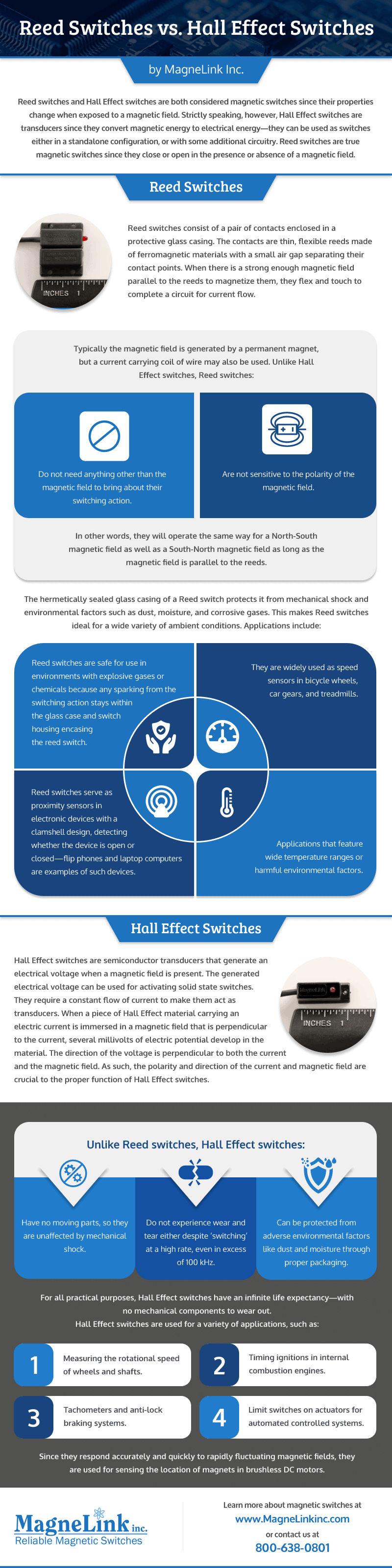
Reed switches and Hall Effect switches are both considered magnetic switches since their properties change when exposed to a magnetic field. Strictly speaking, however, Hall Effect switches are transducers since they convert magnetic energy to electrical energy—they can be used as switches with some additional circuitry. Reed switches are true magnetic switches since they close or open in the presence or absence of a magnetic field.
Reed and Hall Effect switches are ubiquitous not only in electronic devices like cell phones and computers, but also in electromechanical systems like automobile control circuits and fluid control systems. System designers weigh many factors before considering Reed switches and Hall Effect switches for an application.
Reed Switches
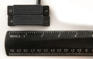
Reed switches consist of a pair of contacts enclosed in a protective glass casing. The contacts are thin, flexible reeds made of ferromagnetic materials with a small air gap separating their contact points. When there is a strong enough magnetic field parallel to the reeds to magnetize them, they flex and touch to complete a circuit for current flow.
Typically the magnetic field is generated by a permanent magnet, but a current carrying coil of wire may also be used. Unlike Hall Effect switches, Reed switches:
Do not need anything other than the magnetic field to bring about their switching action.
Are not sensitive to the polarity of the magnetic field.
In other words, they will operate the same way for a North-South magnetic field as well as a South-North magnetic field as long as the magnetic field is parallel to the reeds.
The hermetically sealed glass casing of a Reed switch protects it from mechanical shock and environmental factors such as dust, moisture, and corrosive gases. This makes Reed switches ideal for a wide variety of ambient conditions. Applications include:
Reed switches are safe for use in environments with explosive gases or chemicals because any sparking from the switching action stays within the glass case and switch housing encasing the reed switch.
They are widely used as speed sensors in bicycle wheels, car gears, and treadmills.
Reed switches serve as proximity sensors in electronic devices with a clamshell design, detecting whether the device is open or closed—flip phones and laptop computers are examples of such devices.
Applications that feature wide temperature ranges or harmful environmental factors.
Hall Effect Switches
Hall Effect switches are semiconductor transducers that generate an electrical voltage when a magnetic field is present. The generated electrical voltage can be used for activating solid state switches. They require a constant flow of current to make them act as transducers.
When a piece of Hall Effect material carrying an electric current is immersed in a magnetic field that is perpendicular to the current, several millivolts of electric potential develop in the material. The direction of the voltage is perpendicular to both the current and the magnetic field. As such, the polarity and direction of the current and magnetic field are crucial to the proper function of Hall Effect switches.
Unlike Reed switches, Hall Effect switches:
Have no moving parts, so they are unaffected by mechanical shock.
Do not experience wear and tear either despite ‘switching’ at a high rate, even in excess of 100 kHz.
Can be protected from adverse environmental factors like dust and moisture through proper packaging.
For all practical purposes, Hall Effect switches have an infinite life expectancy—with no mechanical components to wear out.
Hall Effect switches are used for a variety of applications, such as:
Measuring the rotational speed of wheels and shafts.
Timing ignitions in internal combustion engines.
Tachometers and anti-lock braking systems.
Limit switches on actuators for automated controlled systems.
Since they respond accurately and quickly to rapidly fluctuating magnetic fields, they are used for sensing the location of magnets in brushless DC motors.
Magnetic Switches from Magnelink
To summarize, both Reed switches and Hall Effect switches are activated by magnetic fields—the former as a classical switch and the latter as a transducer. Reed switches do not need any additional circuitry for switching, while Hall Effect switches do. There are significant differences between the two in sensitivity, switched load capacity, and life expectancy.
Magnelink has been a supplier of reliable, high-quality magnetic switches at affordable prices for over 25 years. We specialize in providing standard and custom switches that meet our customer’s specific needs. Contact us today with your Reed switch vs. Hall Effect switch questions.
If you’ve ever used a laptop or a flip phone, you may have wondered how the screen goes dormant once you close the device. Or maybe you’re curious about why your tablet screen turns on every time you open its protective cover. At the heart of these functions is an ingenious device called a reed switch.
What is a reed switch? Reed switches open and close electrical circuits when subjected to magnetic fields. For example, laptops usually have magnets at the top of the screen and the bottom of the keyboard; when the laptop is open, the magnets are far apart from each other, but when it closes, the magnets connect, interrupting the electrical circuit powering the laptop and causing it to enter sleep mode.
Reed switches appear in a wide range of applications, ranging from pacemakers to automotive exhaust sensors to toy lightsabers. Below, we’ve outlined the technology involved in building reed switches, as well as some of their most common applications.
What Is a Reed Switch?
A reed switch is a type of electrical switch with a magnetic-based actuation method. It contains two or three thin and flexible metal wires or blades (i.e., reeds) that are either touching or positioned a few microns apart within a hermetically sealed glass housing. The reeds serve as the switch’s contacts. When the switch is brought in close proximity to a magnetic field, the contacts either move apart or together, depending on whether the switch has a normally closed or normally open design.
The idea for reed switches was first proposed by Leningrad Electrotechnical University professor V. Kovalenkov in 1922. In 1936, Walter B. Elwood of Bell Laboratories designed the first reed switch. By 1938, experimental reed switches were integrated into coaxial cables to switch the cable’s center conductor. In 1940, the first reed switches became available to the public. Today, reed switches find application in many devices and systems, such as mobile phones, industrial equipment, automotive systems, and computers.
How Do Reed Switches Work?
Click to view full-size.
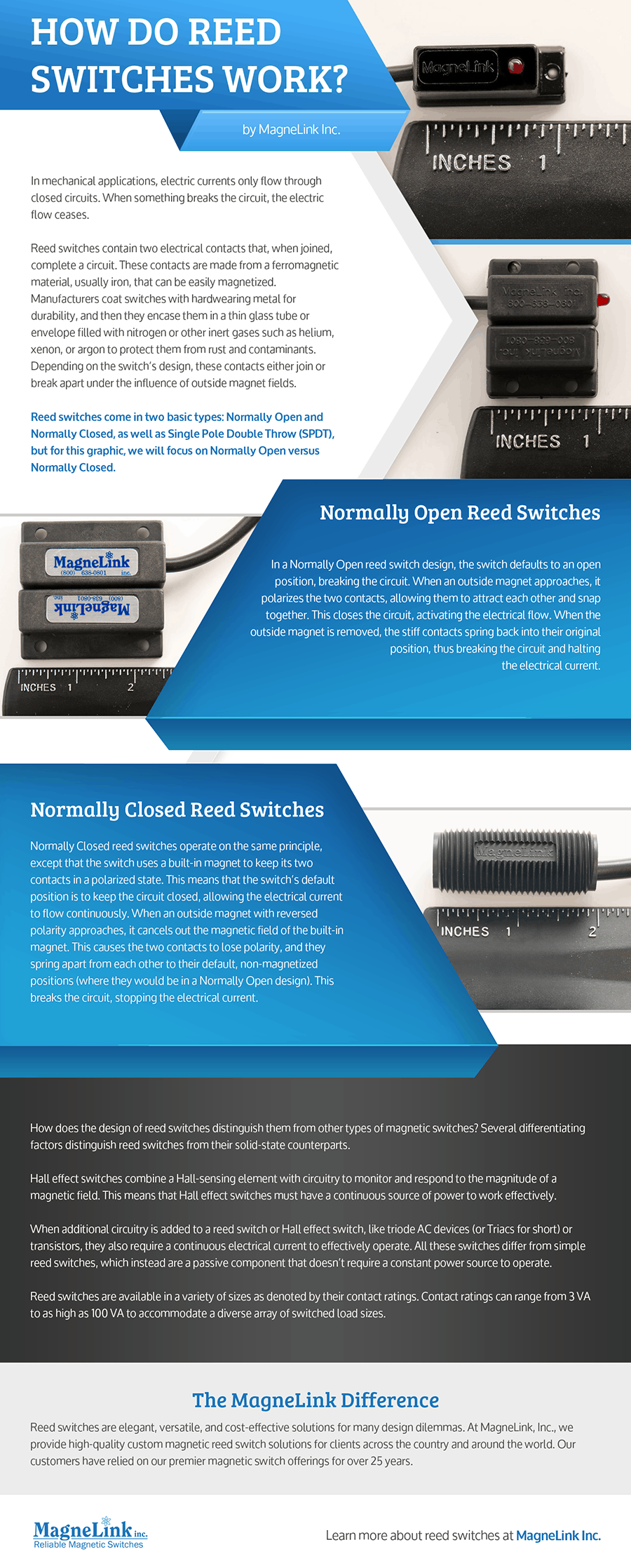
In mechanical applications, electric currents only flow through closed circuits. When something breaks the circuit, the electric current flow ceases.
Reed switches contain two electrical contacts that, when joined, complete a circuit. These contacts are made from a ferromagnetic material, usually iron, that can be easily magnetized. Manufacturers coat switches with hardwearing metal for durability, and then they encase them in a thin glass tube or envelope filled with nitrogen or other inert gases such as helium, xenon, or argon to protect them from rust and contaminants. Depending on the switch’s design, these contacts either join or break apartunder the influence of outside magnet fields.
Reed switches come in two basic types: Normally Open and Normally Closed.
Normally Open Reed Switches
In a Normally Open reed switch design, the switch defaults to an open position, breaking the circuit. When an outside magnet approaches, it polarizes the two contacts, allowing them to attract each other and snap together. This closes the circuit, activating the electrical flow. When the outside magnet is removed, the stiff contacts spring back to their original position, thus breaking the circuit and halting the electrical current.
Normally Closed Reed Switches
Normally Closed reed switches operate on the same principle, except that the switch uses a built-in magnet to keep its two contacts in a polarized state. This means that the switch’s default position is to keep the circuit closed, allowing the electrical current to flow continuously. When an outside magnet with reversed polarity approaches, it cancels out the magnetic field of the built-in magnet. This causes the two contacts to lose polarity, and they spring apart from each other to their default, non-magnetized positions (where they would be in a Normally Open design). This breaks the circuit, stopping the electrical current.
How does the design of reed switches distinguish them from other types of magnetic switches? Several differentiating factors distinguish reed switches from their solid-state counterparts.
Hall effect switches combine a Hall-sensing element with circuitry to monitor and respond to the magnitude of a magnetic field. This means that Hall effect switches must have a continuous source of power to work effectively.
When additional circuitry is added to a reed switch or Hall effect switch, like triode AC devices (or Triacs for short) or transistors, they also require a continuous electrical current to effectively operate. All these switches differ from simple reed switches, which instead are a passive component that doesn’t require a constant power source to operate.
Reed switches are available in a variety of sizes as denoted by their contact ratings. Contact ratings can range from 3 VA to as high as 100 VA to accommodate a diverse array of switched load sizes.
Benefits of Using Reed Switches
Reed switches use much less power than other electronic switch alternatives. Their simple design also makes it much easier to test them out of circuit.
Reed switches come with a host of additional benefits, such as:
Reliability and durability
Reed switches’ straightforward designs mean that they malfunction less often than other circuits, and their protective casings ensure that they can function in a variety of environments. These factors mean that reed switches can operate effectively for decades. Because of this, they’re frequently employed in digital on/off applications like door-closure detectors. A reed switch can have a life spanning tens of millions of switching cycles.
Precision in magnetic sensitivity
Reed switches’ magnetic sensitivity switch points offer higher levels of precision compared with solid-state sensors. This makes reed switches the optimal choice for applications that operate in highly variable environments.
Simple customization
Solid-state switches generally come in one-size-fits-all formats. In contrast, due to the inherent simplicity of their design, you can easily customize reed switches to fit the specifications of each end product.
Reed Switch Design Guide
Reed Switches and Application Fit
When implementing reed switches, engineers should consider the end product’s design requirements. Below are some of the most crucial factors influencing reed switch design.
Electrical requirements
Engineers should determine the maximum switching current, voltage, and power that reed switch contacts can withstand. Contact arcing, or electrical discharge that crosses the gap between separated contacts, can damage the switching components and cause metal transfer, reducing the switch’s life span.
Engineers should also consider whether the reed switch will operate under AC or DC loads, what the minimum switching power will be, and whether the reed switch will fulfill its life expectancy under projected electrical loads.
Environmental factors
Reed switches can operate in a variety of settings. However, it’s important to determine the likely environment for end product use and select the proper switches for the design accordingly.
Reed switches are most susceptible to shock and vibration along the axis on which the switching components move. If excessive mechanical shock is expected to occur regularly when the switch is put into use, care should be taken to choose an appropriately sized reed switch that can best hold up to expected impact. In extreme cases, it may be better to consider using a Hall effect switch as it does not employ any mechanical contacts in its solid-state design.
Engineers should carefully consider the possibility of contact with or influence from outside magnetic fields or ferrous materials. For example, will nearby coils, motors, or batteries disrupt the switch’s magnetic field? If so, this could lead to unpredictable behavior, and steps should be taken to remove any of these stray magnetic fields from the area where the switch is in use.
Life Expectancy of Reed Switches
Compared to other types of switches, the life expectancy for reed switches is considerably longer. Since the contacts experience a relatively small range of mechanical motion, they rarely succumb to material fatigue.
Operating voltage is the main factor that affects the overall lifespan of a reed switch. Most reed switches are engineered for use in relatively low currents.
Other factors that might affect life expectancy include:
DC vs. AC loads
Contact arcing
Vibration and shock
Magnetic interference from other sources
The MagneLink Difference
Reed switches are elegant, versatile, and cost-effective solutions for many design dilemmas. At MagneLink, Inc., we provide high-quality custom magnetic reed switch solutions for clients across the country and around the world. Our customers have relied on our premier magnetic switch offerings for over 30 years.
If you’d like to learn more about our reed switch selection, contact us today. Once you experience the MagneLink difference, we’re sure that you won’t want to go anywhere else.


 The
The 


 Reliability and durability
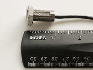 Electrical requirements