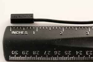
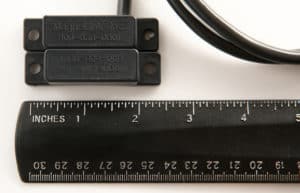
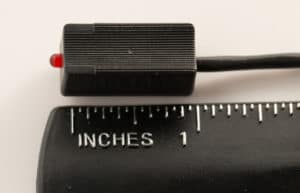
What is a Hall Effect Sensor?
Comments Off on What is a Hall Effect Sensor?Hall Effect sensors are used for detecting and measuring proximity, position, and speed, through their ability to sense magnetic fields. As non-contact sensors, they are useful for measuring AC and DC currents. This blog will explain the principles behind Hall effect sensors and their industrial applications.
What is a Hall Effect Sensor?

When electric current traverses the sensor is in a magnetic field, the detector will register a small voltage. This voltage can be used to measure fluctuations in the magnetic field caused by changes in position, proximity, pressure, speed, temperature, or other factors.
Since Hall Effect sensors do not have any moving parts, they are more robust and durable than reed switches. However, they are also more expensive since they need a constant electrical current flowing through them.
Types of Hall Effect Sensors
Hall Effect sensors are broadly divided into two categories: analog and digital. The analog sensors produce a continuously varying voltage output while the digital version has just two output voltages: high or low.
Some of the sub-categories for Hall Effect switches include:
Vane-operated
These are digital proximity sensors that detect the presence or absence of a ferrous vane that passes through a gap between the two components of the vane-operated sensor: a permanent magnet and a Hall Effect sensor.
Digital current
This sensor also has two components in close proximity: a Hall Effect sensor and an electromagnet. The magnetic field produced by the electromagnet when current passes through its coils changes the output of the Hall Effect sensor.
Linear current
This is similar to the digital current sensor, except the output is analog.
Closed-loop current
Also called null balance current sensors, they work by nullifying the magnetic field being sensed by driving a current derived from the sensor output. Though they have excellent response, accuracy, and linearity characteristics, they are bulky and expensive due to the additional components required to generate the null balance current.
Gear tooth
As the name implies, these sensors detect the teeth of a gear as they pass by the sensor. Gear tooth sensors are similar to vane operated sensors but have additional circuitry to accurately measure speed. They are used in a variety of counting and speed sensing applications.
Applications for Hall Effect Sensors
As evident from the various categories of sensors mentioned above, Hall Effect sensors can be used for a wide range of applications, such as:
- Automated product handling
- CNC equipment
- Compactors / Balers
- Motion detectors
- Position sensors (ex: doors)
- Robotics (ex: limit switches)
- Safety interlocks (ex: defeat resistant safety switches)
Considerations for Hall Effect Sensor Design
The important factors that influence the design of a Hall Effect sensor include:
- Magnetic fields. The field produced by a magnet depends on its shape and size, the material used to construct it, the material in the path of the magnetic flux, and whether it is used as a unipolar or bipolar magnet.
- Electrical considerations. What is the maximum current the sensor will have to handle? Is there a constant voltagesupply available to supply the sensor? What is the maximum flux it will experience? Should the output be analog or digital?
- Operating environment. The temperature range over which the sensor must operate is an important environmental factor. Outdoor applications may require weatherproof housing for protection from rain and snow.
- As with all industrial components, cost is an important issue with Hall Effect sensors. The operating temperature range, packaging requirements, precision and sensitivity of the output, and other features required by the application determine the final cost of the Hall Effect sensor.
Hall Effect Sensors from MagneLink
MagneLink has over 25 years of experience designing high-quality custom magnetic switches and sensors. Get in touch with us for all your Hall Effect magnetic switch requirements.
TRIAC Circuits: Basics & Applications
Comments Off on TRIAC Circuits: Basics & ApplicationsThe term “TRIAC” stands for triode for alternating current. As suggested by its name, this electronic component is commonly used as a control element in alternating current (AC) circuits.
TRIACs are semiconductor devices that feature three terminals. They operate by using one terminal—i.e., the gate—to trigger the flow of electrical current through the other two terminals—i.e., the main terminals or anodes. Although these devices are similar to other electronic switches such as silicon controlled rectifiers (SCR), unlike some of these alternatives, they can conduct equally well in both directions.
TRIACs often find application as switches in a wide range of electrical equipment, such as lamps, fans, and motors. Regardless of their application, all TRIACs employ the basic operating principles outlined above. Beyond these shared characteristics, they are generally categorized into ones used for simple TRIAC switch circuits or TRIAC variable power (or dimmer) circuits.
Functions of TRIAC Switches
TRIACs are used in several different ways, including as:
Simple Electronic Switches
In this application, the TRIAC is triggered by an AC voltage at its gate. A resistor is used in series with the gate to limit the current flow to the terminal. The TRIAC allows current to flow in either direction with flow changing with the polarity of the gate voltage. The gate voltage can be derived from the AC voltage applied to the TRIAC’s load terminals. If the application requires current flow in only one direction, a diode is connected in series to the gate to convert the AC voltage to DC. In this configuration, the current flow through the TRIAC, for a given load, is fixed.
Power Level or Dimmer Controllers
The gate trigger for this use case is more sophisticated since it involves varying its phase in relation to the load voltage. The trigger voltage is derived from the load voltage, but with a phase shift applied to it. The phase-shifting circuitry consists of a variable resistor and a capacitor. The capacitor voltage is used as the trigger voltage, which has its phase varied by changing the variable resistor. Frequently, a DIAC (diode for AC) switch is connected between the capacitor and the TRIAC’s gate to achieve a sharp turning ON of the TRIAC.
TRIACs find use in a number of electrical applications, including as:
- Dimmer switches for lamps
- Output controllers for electric heaters
- Speed controllers for motors
Issues With TRIAC Circuits & the Solutions
When employing TRIAC circuits, it is important to be aware of the common issues encountered and how to resolve them. Some of the issues that come with using TRIAC circuits include:
Rate Effect
This effect refers to the unintended turning on of the TRIAC due to a sudden change in the voltage across its main terminals. The issue is resolved by connecting a resistor-capacitor (RC) snubber circuit between the main terminals.
Backlash Effect
Backlash occurs in phase control circuits when the resistance is set to the maximum to reduce the power levels of the connected device to the minimum. The effect is caused by the lack of a discharge path for the TRIAC’s inherent capacitance across its load terminals and prevents the connected device from turning on. The solution is to provide a discharge path by connecting a high-value resistor in series with the DIAC or a capacitor between the gate and main terminals.
Non-Symmetrical Firing
In phase control circuits, this issue occurs due to TRIACs having different turn-on voltages for each direction. This design leads to a poor electromagnetic radiation profile for the TRIAC. This issue is resolved by using a DIAC in series with the TRIAC’s gate, which evens out the firing characteristics of the TRIAC.
Harmonic Filtering
Since the TRIAC turns on when the voltage across its terminals is not zero, it generates harmonics that make it unsuitable for use in sensitive electronic equipment, such as wireless communications circuitry. Using a harmonic filter suppresses electromagnetic interference.
Contact MagneLink for Your TRIAC Switch Needs
At MagneLink, Inc., we integrate TRIACs with our magnetic switches in our MLT, MLP, and MLU housings. Each of these styles is suitable for different applications. For example, MLT housings are appropriate for use in harsh environments, MLP housings are good for rugged applications, and MLU housings have a threaded housing that is more suitable for flush mounting.
To learn more about our TRIAC style switch offerings, check out our products page. Contact us today for information or a quote on a custom-built switch solution.
Hall Effect Guide
Comments Off on Hall Effect GuideOver 100 years ago, the Hall effect was identified. However, it is only within the last three decades that practical uses of this effect have been developed. Some of its first applications include use in microwave sensors in the 1950s and solid-state keyboards in the 1960s. Since the 1970s, Hall effect sensing devices have found their way into a wide range of industrial and consumer products, such as sewing machines, automobiles, machining tools, medical equipment, and computers.
Before examining the five key industrial applications of Hall effect sensors, it is necessary to define them, their function, and their various classifications.
What Is the Hall Effect?
In 1879, physicist Edwin Hall discovered the effect of magnetic fields on semiconductors with a unidirectional current. When a conductor and field interact perpendicularly, the voltage measurement at right angles to the current’s movement later became known as the Hall effect.
To visualize this effect, picture the conductor’s current as water moving through a pipe. The magnetic field would push or pull the water to one side of the pipe. If you imagine the water and pipe as electricity through a wire, you can see the Hall effect in action. The particles in the current and the magnetic field are measurable.
In the semiconductor industry, the Hall effect has enabled people to determine whether the current through a material is carried by positive particles (as with semiconductors) or negative particles (which is the case with metals). As a result, scientists have classified chemicals, developed refined semiconductive materials, and measured magnetic fields in various environments.
Today, Hall effect devices are commonly used to measure magnetic fields by seeing the effect they have on a known current. Because a magnetic field can alter the course of a flowing unidirectional current, one side of the wire will have a greater negative charge than the other side, and that change results in measurable voltage. The voltage increases proportionately to the strength of the field.
Applications of the Hall Effect
The Hall effect has applications for researchers, industrial facilities, commercial businesses, the automotive industry, and more. Hall sensors can measure voltage, current, and magnetic fields in manufacturing, inspecting, and testing purposes. These are some of the most common applications of the Hall effect.
Magnetometers
Magnetometers, or Hall probes, measure the strength of magnetic fields, often for permanent magnets in engineering design evaluations. They can also be used to detect magnetic flux leakage in pipes and storage tanks.
Magnetic Field Detection
Magnetic field sensors and detection equipment can pick up the presence of magnetic fields and determine their magnitude. Once the fields are detected, a trigger can provide signals and data or switch power to a circuit.
Current and Voltage Sensing and Measurement
Sensors use the Hall effect to detect or measure direct currents. A Hall device can detect the presence of a magnetic field. In some cases, a Hall device can measure the voltage and determine the current, displaying it as a readable signal.
Position and Motion Sensing
In the case of magnetic field detection, this function is used widely in industrial and commercial equipment and machinery. A Hall effect sensor has the advantage of no mechanically moving components in detecting the presence of a magnetic field. They are used commonly as limit switches.
Complex machinery and vehicles also benefit from the Hall effect. When they detect fluctuations in voltage, these sensors transmit signals that can be implemented in tachometers, anti-lock braking systems in vehicles, and material handling assemblies.
Ignition Timing
The Hall effect’s capabilities to sense or control motion are crucial to proper ignition timing in internal combustion engines. Ignition timing is the precise release of a spark into a combustion chamber based on the position of the piston and the corresponding crankshaft angle.
What Is a Hall Effect Sensor?
Hall effect sensors are magnetic components that convert magnetically encoded information—such as position, distance, and speed—so that electronic circuits can process it. They are generally classified based on their manner of output or means of operation.
Output Classifications
Separating Hall effect sensors by voltage output results in two sensor classifications: digital sensors and analog sensors.
Digital Output Hall Effect Sensors
Digital output Hall effect sensors are primarily used in magnetic switch applications to provide a digital voltage output. In this way, they provide an ON or OFF input signal to the system.
The primary distinction of a digital output Hall effect sensor is its means of controlling voltage output. Instead of the power supply providing the saturation limits, digital output sensors have a Schmidt-trigger with built-in hysteresis connected to the op-amp. This switch turns the sensor output off whenever magnetic flux exceeds its pre-set limits and back on when flux stabilizes.
Analog (or Linear) Output Hall Effect Sensors
An analog type sensor provides a continuous voltage output that increases when a magnetic field is stronger and decreases when it is weaker. Thus, the output voltage or amplification of an analog Hall effect sensor is directly proportional to the intensity of the magnetic flux passing through it.
Operation Classifications
In addition to classifying them by output, Hall effect sensors can be separated into categories based on the manner of operation, which includes:
Bipolar Hall Effect Sensors
This is a type of digital sensor, which operates using either positive or negative magnetic fields. Either the positive or negative magnetic field of the magnet activates the sensor. In this configuration, a switch using a bipolar Hall effect sensor is triggered in much the same way as a traditional Reed switch. However, the Hall effect switch has the added advantage of having no mechanical contacts, making it more durable in rugged environments.
Unipolar Hall Effect Sensors
In contrast to a bi-polar sensor, this type of digital sensor is triggered only by one pole (either North or South) of the magnet. Using a unipolar Hall effect sensor in a switch allows the set up to be more particular and only activate when exposed to a specific magnetic pole.
Direct Angle and Vertical Angle Hall Effect Sensors
More advanced Hall effect sensors focus on components of the magnetic field other than the poles. For example, direct angle sensors measure the sine and cosine measurements of the magnetic field, while vertical angle sensors analyze the components of the magnetic field that are parallel—rather than perpendicular—to the plane of the chip.
Five Key Applications of Hall Effect Sensors
Hall effect sensors find use in a broad range of applications across five major industries, which are:
Automotive and Automotive Safety
The automotive and automotive safety industries use both digital and analog Hall effect sensors in a variety of applications.
Examples of digital Hall effect sensor applications in the automotive industry include:
- Sensing seat and safety belt position for air-bag control
- Sensing the angular position of the crankshaft to adjust the firing angle for spark plugs
Some examples of the use of analog type sensors include:
- Monitoring and controlling wheel speeds in anti-lock braking systems (ABS)
- Regulating voltage in electrical systems
Appliances and Consumer Goods
The appliance and consumer goods industries integrate various types of Hall effect sensors in numerous product designs. For example:
- Digital unipolar sensors help washing machines maintain their balance during wash cycles.
- Analog sensors serve as availability sensors for power supplies, motor control indicators and shut-offs on power tools, and paper feed sensors in copier machines.
Fluid Monitoring
Digital Hall effects sensors are commonly used for monitoring flow rate and valve position for manufacturing, water supply and treatment, and oil and gas process operations. In fluid monitoring applications, analog Hall effect sensors are also used to detect diaphragm pressure levels in diaphragm pressure gauges.
Building Automation
In building automation operations, contractors and subcontractors integrate both digital and analog Hall effect sensors.
Digital, proximity-sensing devices are often used in the design of:
- Automatic toilet flushing mechanism
- Automatic sinks
- Automatic hand dryers
- Building and door security systems
- Elevators
Analog sensors are used for:
- Motion sensing lighting
- Motion sensing cameras
Personal Electronics
This is another area where both analog and digital Hall effect sensors continue to grow in popularity.
Applications for digital sensors include:
- Motor control devices
- Timing mechanisms in photography equipment
Applications for analog sensors include:
- Disk drives
- Power supply protectors
Contact MagneLink Today
As outlined above, Hall effect sensors—both analog and digital—find application in a broad range of devices, equipment, and systems across a variety of industries.
At MagneLink, we develop and manufacture high-quality magnetic switches, including switches that employ Hall effect sensors. To learn more about our Hall switches and their applications, contact us today.


