TRIAC Circuits: Basics & Applications
Comments Off on TRIAC Circuits: Basics & ApplicationsThe term “TRIAC” stands for triode for alternating current. As suggested by its name, this electronic component is commonly used as a control element in alternating current (AC) circuits.
TRIACs are semiconductor devices that feature three terminals. They operate by using one terminal—i.e., the gate—to trigger the flow of electrical current through the other two terminals—i.e., the main terminals or anodes. Although these devices are similar to other electronic switches such as silicon controlled rectifiers (SCR), unlike some of these alternatives, they can conduct equally well in both directions.
TRIACs often find application as switches in a wide range of electrical equipment, such as lamps, fans, and motors. Regardless of their application, all TRIACs employ the basic operating principles outlined above. Beyond these shared characteristics, they are generally categorized into ones used for simple TRIAC switch circuits or TRIAC variable power (or dimmer) circuits.
Functions of TRIAC Switches
TRIACs are used in several different ways, including as:
Simple Electronic Switches
In this application, the TRIAC is triggered by an AC voltage at its gate. A resistor is used in series with the gate to limit the current flow to the terminal. The TRIAC allows current to flow in either direction with flow changing with the polarity of the gate voltage. The gate voltage can be derived from the AC voltage applied to the TRIAC’s load terminals. If the application requires current flow in only one direction, a diode is connected in series to the gate to convert the AC voltage to DC. In this configuration, the current flow through the TRIAC, for a given load, is fixed.
Power Level or Dimmer Controllers
The gate trigger for this use case is more sophisticated since it involves varying its phase in relation to the load voltage. The trigger voltage is derived from the load voltage, but with a phase shift applied to it. The phase-shifting circuitry consists of a variable resistor and a capacitor. The capacitor voltage is used as the trigger voltage, which has its phase varied by changing the variable resistor. Frequently, a DIAC (diode for AC) switch is connected between the capacitor and the TRIAC’s gate to achieve a sharp turning ON of the TRIAC.
TRIACs find use in a number of electrical applications, including as:
- Dimmer switches for lamps
- Output controllers for electric heaters
- Speed controllers for motors

Issues With TRIAC Circuits & the Solutions
When employing TRIAC circuits, it is important to be aware of the common issues encountered and how to resolve them. Some of the issues that come with using TRIAC circuits include:
Rate Effect
This effect refers to the unintended turning on of the TRIAC due to a sudden change in the voltage across its main terminals. The issue is resolved by connecting a resistor-capacitor (RC) snubber circuit between the main terminals.
Backlash Effect
Backlash occurs in phase control circuits when the resistance is set to the maximum to reduce the power levels of the connected device to the minimum. The effect is caused by the lack of a discharge path for the TRIAC’s inherent capacitance across its load terminals and prevents the connected device from turning on. The solution is to provide a discharge path by connecting a high-value resistor in series with the DIAC or a capacitor between the gate and main terminals.
Non-Symmetrical Firing
In phase control circuits, this issue occurs due to TRIACs having different turn-on voltages for each direction. This design leads to a poor electromagnetic radiation profile for the TRIAC. This issue is resolved by using a DIAC in series with the TRIAC’s gate, which evens out the firing characteristics of the TRIAC.
Harmonic Filtering
Since the TRIAC turns on when the voltage across its terminals is not zero, it generates harmonics that make it unsuitable for use in sensitive electronic equipment, such as wireless communications circuitry. Using a harmonic filter suppresses electromagnetic interference.
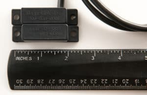
Contact MagneLink for Your TRIAC Switch Needs
At MagneLink, Inc., we integrate TRIACs with our magnetic switches in our MLT, MLP, and MLU housings. Each of these styles is suitable for different applications. For example, MLT housings are appropriate for use in harsh environments, MLP housings are good for rugged applications, and MLU housings have a threaded housing that is more suitable for flush mounting.
To learn more about our TRIAC style switch offerings, check out our products page. Contact us today for information or a quote on a custom-built switch solution.